
Call us now:


Tool Steel Quality Assurance
Ultrasonic Testing for Internal Defects in H13 Tool Steel
Ultrasonic testing can screen H13 tool-steel bars and blocks for internal discontinuities before expensive machining and heat treatment begin.
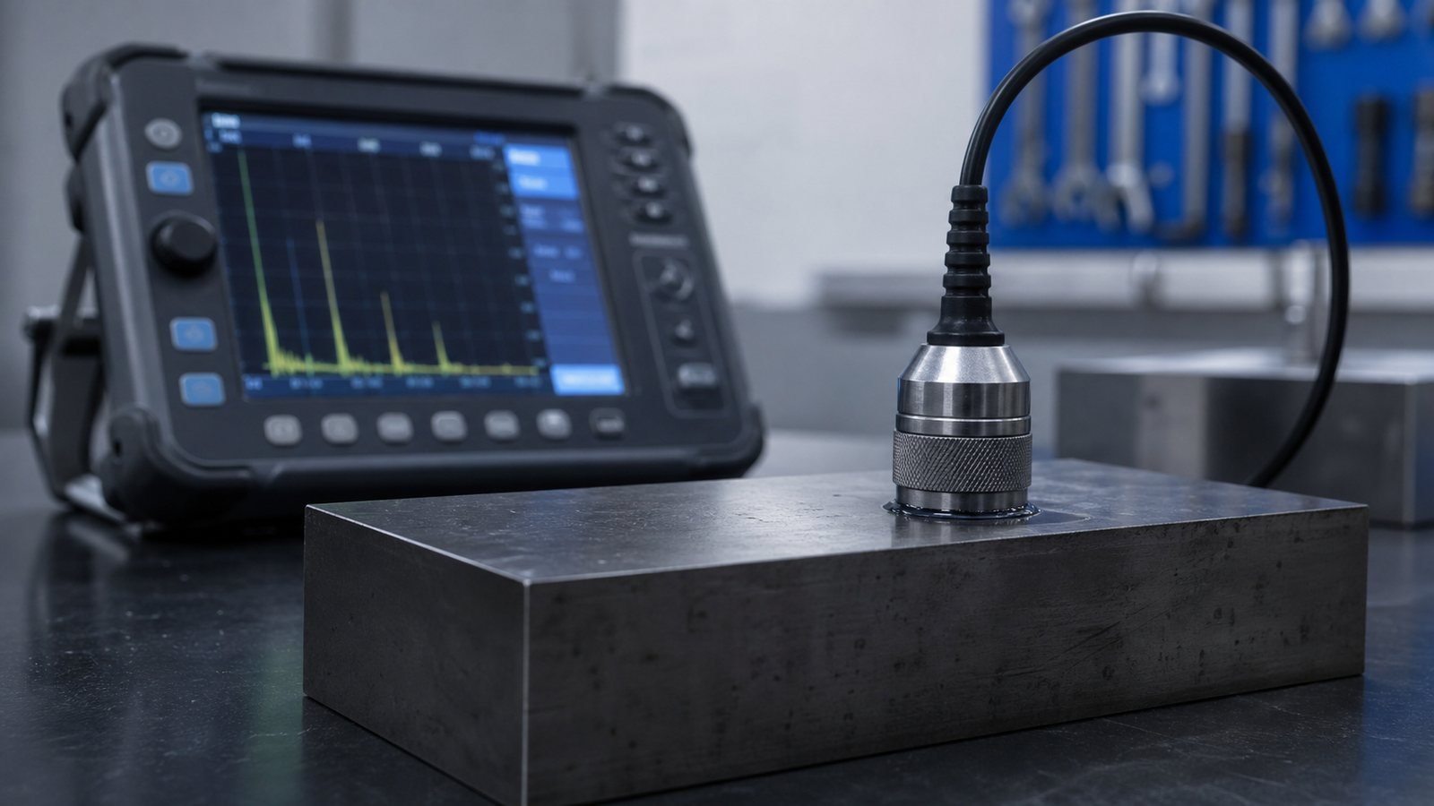
Quick answer: Ultrasonic testing sends high-frequency sound into H13 tool steel and evaluates reflected signals. With a qualified procedure, suitable calibration blocks and defined acceptance criteria, UT can detect or characterize internal discontinuities such as inclusions, porosity, laps, cracks and areas of poor sound transmission.
Why inspect H13 before machining
H13 is a chromium-molybdenum-vanadium hot-work tool steel used for dies, extrusion tooling, hot shears and other thermally cycled components. These parts can require substantial stock removal, heat treatment and finishing. Finding a significant internal discontinuity after that value has been added is costly.
UT is attractive because it can examine volume without cutting the product. It is not a universal “defect detector”: the test sensitivity, resolution and coverage depend on frequency, probe size, surface, sound path, microstructure and the written procedure.
How pulse-echo UT works
A transducer introduces an ultrasonic pulse through a couplant. The instrument displays echoes from interfaces such as the back wall or an internal reflector. A discontinuity may create a new echo, reduce the back-wall signal or scatter sound. Straight-beam compression-wave testing is common for bars and blocks, while angled or focused techniques may be added for specific geometries.
The inspector establishes time base and sensitivity with reference reflectors in a calibration block. Distance-amplitude correction or equivalent methods compensate for sound-path effects. The response is then evaluated against the governing acceptance procedure, not against an arbitrary screen height.
Potential indications in tool steel
| Possible source | Typical concern | UT observation |
|---|---|---|
| Nonmetallic inclusion cluster | Reduced fatigue or fracture resistance | Discrete or distributed echoes; possible back-wall loss |
| Shrinkage or porosity | Local loss of soundness | Scattered indications or attenuated back wall |
| Internal crack | High stress concentration | Strong directional reflection when favorably oriented |
| Segregation / coarse structure | Nonuniform response to heat treatment | Elevated attenuation or noise; requires metallurgical correlation |
| Surface condition / geometry | False or masked response | Near-surface noise, multiple echoes or incomplete coupling |
Procedure variables that matter
Frequency is a tradeoff. Higher frequency can improve resolution but attenuates more in coarse or highly scattering material. Lower frequency penetrates longer sound paths but may not resolve small reflectors. Surface roughness and curvature affect coupling, and a dead zone near the entry surface can limit detection. Multiple scan directions improve the chance of intersecting planar flaws.
The procedure should define equipment, probes, couplant, calibration, reference reflectors, scanning grid, overlap, sensitivity, transfer correction, recording threshold and acceptance criteria. Personnel qualification and equipment verification must follow the contractual standard.
Interpreting and confirming indications
Signal amplitude alone does not give actual flaw size because orientation, roughness and beam interaction change reflectivity. An inspector may map the indication from several directions, measure its position and apparent extent, and compare it with a distance-amplitude curve. Where disposition is important, complementary surface examination, local machining, metallography or another method may be required.
The report should identify the tested volume, inaccessible zones, procedure and revision, calibration reference, sensitivity, scan directions, indications and disposition. “UT passed” without the acceptance class or report basis provides limited procurement value.
Ordering H13 with UT
State the H13 material standard, product form, size, annealed condition, machining allowance, required UT standard and acceptance class, test stage, reporting and traceability. Confirm whether end zones, center zones or near-surface areas require a special technique.
UT should complement, not replace, chemistry, hardness, microstructure, mechanical-property and heat-treatment controls. Together they reduce the chance that an internally unsound or metallurgically unsuitable block enters a critical tooling route.
Conclusion
A well-designed UT program turns internal soundness from an assumption into a documented acceptance decision. The value lies in a qualified method and agreed criteria, not merely in placing a probe on the steel.
Technical references
Discuss Your Requirement with SAKYMETAL
Provide the H13 bar or block size, governing specification, machining allowance, UT standard and acceptance class, required report and heat-treatment route.
Next step: view related products or contact SAKYMETAL.
Technical note: This article is a general selection guide. Final material, condition, dimensions, testing and acceptance criteria shall follow the purchase order, governing specification and material test certificate.